005 2022-05-05
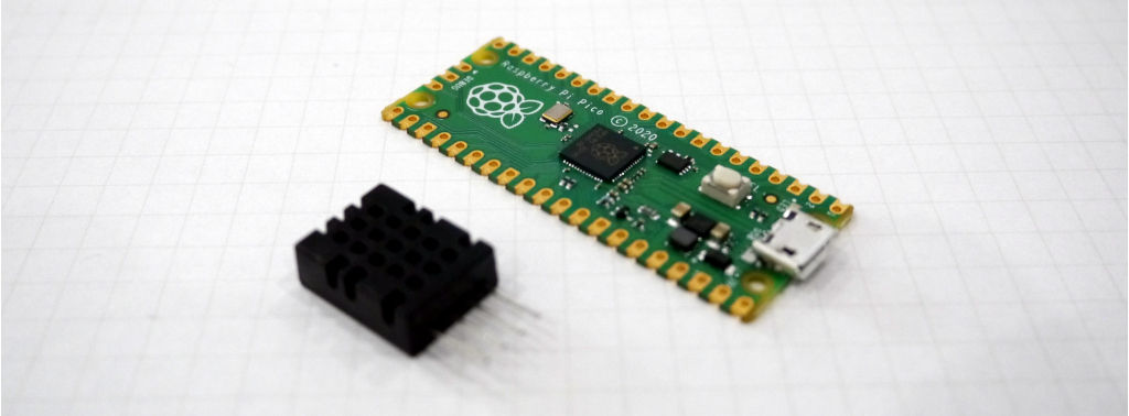
One of my latest projects involved wiring a DHT20 sensor to an RPi Pico (pictured above), and logging the values to a server generating RRD graphs. The project was originally quite simple, but I eventually found myself thinking about feature creep and how things could easily get out of hand. Here, I explain 4 different ways of completing this task, and I'll wrap up with my final thoughts and suggestions.
What is DHT20?
Almost every hardware hacker is familiar with the DHT11 pictured below:
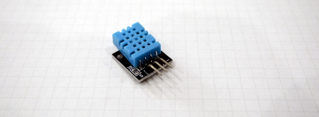
This device is an inexpensive temperature/humidity sensor available standalone, or mounted to a PCB with a few passive components. Its main selling points are: acceptable accuracy (for small projects) and ease of use - connect the 3 pins (GND, VCC, DATA) and start reading the values.
The makers of that sensor later released the DHT20 which has useful improvements: it is more accurate and the data is accessible over I2C. This means you now need 4 pins (GND, VCC, SDA, SCL), but in exchange the data reads can be performed asynchronously rather than blocking in a busy loop.
Let's see how we can obtain that data.
Approach 1: the simplest
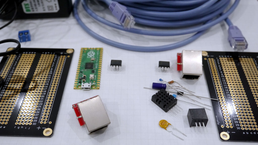
In this approach, our RPi Pico is wired directly to the DHT20 sensor, with a decoupling capacitor across the VCC and GND pins. Only three components are required, and the firmware simply needs to setup the I2C device (0x38), request the data (0xAC, 0x33, 0x00), then read a few bytes.
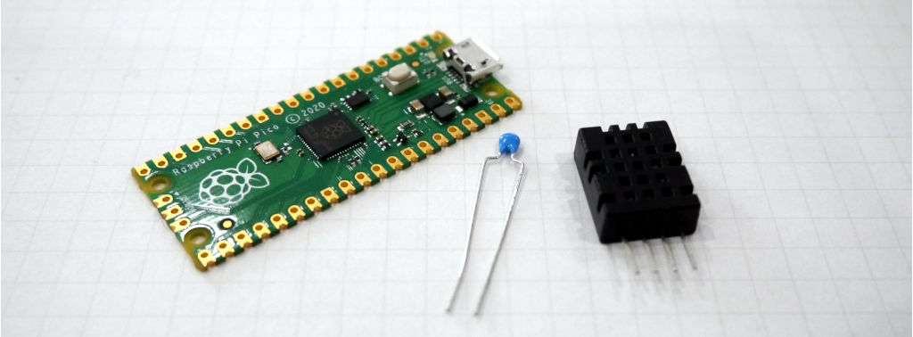
This is simple and fantastic. To make it more permanent, the components can be soldered together. It's guaranteed to work as expected and we can move-on to other projects, however...
Approach 2: remote sensor
Here, we realize we're somewhat limited because the DHT20 sensor is tightly coupled to the RPi Pico. Wouldn't it be great if we could mount the sensor in the exact area we want to monitor, while leaving the Pico close to our server?
In this case, we'll need two RJ45 connectors and a CAT-5 cable. To avoid parasitic capacitance, we're limited to short length cables, not more than 1 meter just to be safe. We'll want to ensure the SCL line is in a twisted pair with GND, and the SDA line with VCC. Finally, we'll want to solder the Pico and an RJ45 onto a perfboard, and the other components on another perfboard. We'll use slightly oversized boards for future expansion.
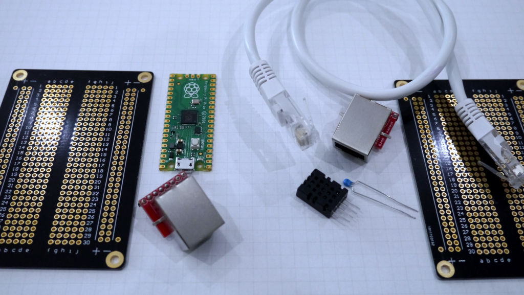
Great! We're getting somewhere. Now connect the CAT-5 cable between the two boards, power up the Pico, and enjoy! This gets the job done in our test environment, however...
Approach 3: really remote sensor
The second approach was good, but it wasn't great. One meter is still relatively short. Wouldn't it be great if the sensor could sit at the other end of the office? say... 10 or 100 meters away? I discussed this approach a year ago in an old blog post.
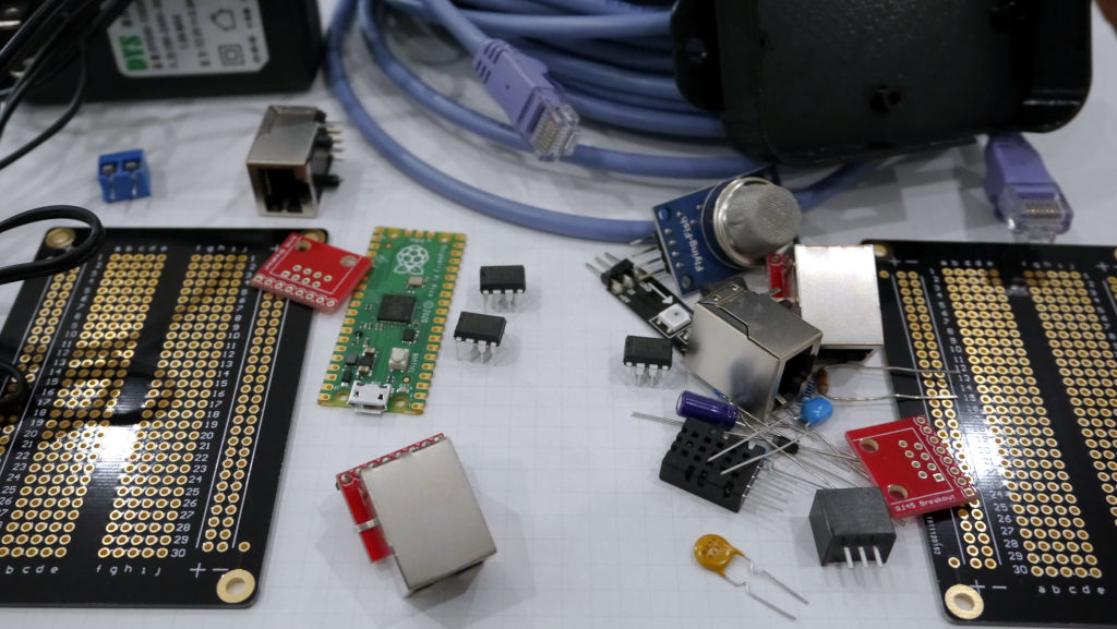
Since we'll see a large voltage drop at the other end of the cable, we'll need to send a higher voltage across the wires, and drop it near the sensor. If we're using RJ45 (8P8C) connectors with builtin LEDs, we'll want them to light up when the DHT20 is powered and when there's activity.
So let's do this: we'll use the 802.3af mode B passive PoE pinouts to connect the devices. We'll dedicate one twisted pair for GND, one for VCC, one for SCL and one for SDA. We'll add some RS-485 ICs to send a differential signal between the RPi Pico and the DHT20 sensor. We'll need a 12V power source and a screw terminal, and we'll feed it into the CAT-6 cable (oops, the CAT-5 is not suitable anymore, so let's upgrade to CAT-6), a DC-DC converter to step the 12V down to 3.3V, a fuse to protect the wiring, a diode to protect ourselves from really dumb mistakes, and some resistors and capacitors here and there.
Phew! Now we've got all these components, and I'm pretty sure we can call it a day because our needs are met and the project is reliable, however...
Approach 4: gas sensor, RGB LED
By now you probably saw this coming. The perfboard still has lots of space for additional components, so why don't we add a gas sensor and an RGB LED? Environmental sensors are ubiquitous, so a simple MQ-xx sensor would make our solution even more useful. The RGB LED (Neopixel?) would be helpful because we can alter its colour based on the status of the sensors.
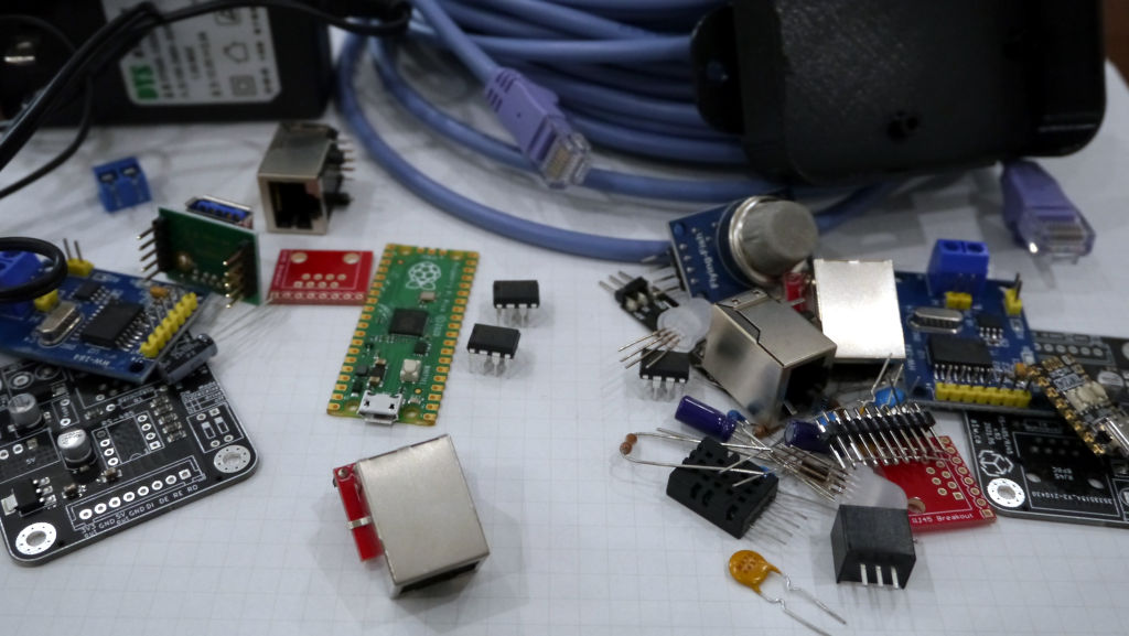
To do this, we'll need to add a handful of additional passive components, but we quickly run into a problem: our CAT-6 has no available wires. Solution: add another RJ45! We won't adhere to the 802.3af standard, so we'll use the additional twisted pairs for the RGB LED and the MQ sensor's analog signal. Of course, we'll need more RS-485 ICs. Furthermore, our perfboard is starting to look quite janky, so at this point we should probably design a PCB in KiCAD and send it to a fab for a small run of pre-production boards. They promise we'll receive them in 2 weeks, so while we wait we'll design a slick enclosure in OpenSCAD, export to STLs and 3D print in different colours and materials.
OK we're done here? Our board has all these wonderful features, it's starting to look quite professional and works better than we imagined, however...
Approach 5: CAN bus
I said there's only 4 approaches, but this is a blog post about feature creep.
And now the holy grail of all Seasoned Electrical Engineers™: CAN bus. The previous approaches were fine, but in reality we all know it's not fine until you're using CAN. This will allow us to reduce the amount of connectors and wires between the two boards, and yes we can still use CAT-6. After all these iterations, our wallet is starting to look a little thin, but we've gained the benefit of a battle-tested industrial protocol, backed by big companies who know what they're doing.
For this setup, we'll need a few new ICs, namely a CAN controller, a couple CAN transceivers, some more passives to adhere to the datasheet, and you guessed it: a new microcontroller which we'll wire directly to the DHT20 (see Approach 1). This microcontroller can also be an RPi Pico, but since we've already designed a PCB in the previous approach, we might as well add-in the RP2040 chip directly. For that we'll also need a crystal oscillator, another diode and fuse, more passives, ferrite beads, LDO converters, status LEDs, inductors, physical switch buttons, pin headers, a USB connector, and an oscilloscope.
Finally, we'll need to program our firmware on the two RPI Picos to transfer sensor data and LED status between each other. A simple serial message should be sufficient and easy to decode at the other end.
And there we have it, feature creep at its best. Of course we could go even further by designing our boards to allow connecting more sensors, or even an LCD. But the exercise was to see how easily electronics projects can get out of hand.
Final thoughts
There is nothing inherently wrong with any of these approaches. Each one works well, but the use-case is the variable.
It's easy to fall in love with flexibility, modularity, and a flurry of features to make the project more exciting, or perhaps more appealing to our Tindie customers. However it's preferable to take a step back at regular intervals, to evaluate our needs and figure out if we're still going in the direction of our original goal. As features creep, so do costs and time.
One technique that works really well for me is to design my project from the start, in KiCAD. Even though it takes more time than "just wiring stuff", there's an important mental exercise in designing the project. It allows me to easily find flaws in my approach, and quickly see if things are getting out of scope for my requirements - without spending money on parts or manufacturing. All feature creep becomes visible in the schematic - so it's easy to consciously decide to throw out the new feature and keep things simple.
I like to decide early-on if the project is something I want to sell, or just make a one-off for myself. In the latter case, a quickly hacked up perfboard is always more than adequate, and a generic 3D printed enclosure can go a long way to making it look good.
As a final note, feature creep isn't necessarily a bad thing. Sometimes a project might take 5x longer to complete, and cost similarly more, but it may be worth it if the end result is much better than some of the junk that's currently available on the market. Engineers should have pride in their work, particularly if it's going up for sale. If that means doing things correctly, following standards, and designing for modularity and repairability, then I'm all for it. But rest assured, if it's just a DIY project - your time will be better spent shipping than toiling away at features you probably won't care about a year from now.
https://blog.a1w.ca/p/2022-05-05-feature-creep-in-electronics-projects
2022-05-07 08:50:25 UTC