003 2021-03-08
Since we're talking about microcontrollers (MCUs), I won't discuss the use of "networking" as we typically know it, which involves RJ-45 connectors, cables, ethernet and a TCP/IP stack on both devices. The use case for that is typically to have two or more computers communicate either directly through a LAN cable, or through some networking equipment such as a hub or switch.
Here I plan to discuss the transmission of raw data, through a custom protocol between a microcontroller and sensors or devices located far away from each other.
Existing information
This topic has been covered in blog posts, on Arduino forums, and on stackexchange, but there's so much information that it can quickly lead to confusion. An online search can yield thousands of results with completely different solutions.
It seems there's no single, correct way of doing it, since each approach has its share of trade-offs.
Before we begin, it's important to figure out our goals:
- Transfer data reliably over at least 10 meters, but possibly 30, 50, even 100m
- Little or no firmware complexity
- Keep the cost at a minimum
- Use the simplest possible approach with the least amount of components
- Don't be tightly coupled to one manufacturer's hardware
- Avoid problems of EMI (interference) and unreliable signals
- Prevent burning down the house or blowing up electronics
For this example use-case, we'll be sending a 24-bit signal from an MCU to a 5 meter WS2812 LED strip located 30 meters away. The signal will contain data to change the colour and brightness of the LEDs. We also want to power the LED strip with 5V DC.
Since we need 5V at the LEDs and our wire is 30m long, we'll see a massive voltage drop across that wire. Ideally we should send 12V or more, and have it stepped-down to 5V using an efficient DC-DC switching voltage regulator. As a side note, the higher the voltage, the less current our LEDs will draw.
Possible solutions for our example use-case
RJ-45
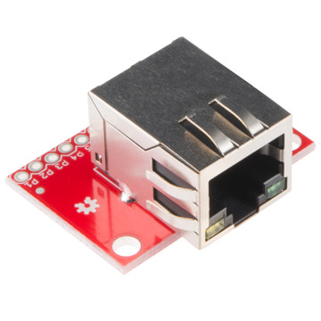 Image is Copyright Sparkfun - CC BY 2.0
Parts list:
- 2x RJ-45 connectors
- 1x 30m LAN cable
- 1x 500mA fuse
My initial research led me to using a pair of RJ-45 connectors and a simple LAN cable. The idea was to send data over one wire (the LAN cable contains 8 wires), power over another wire, and ground over a third wire. This works well over a short distance in a lab environment, but it's unreliable over a longer distance and could lead to strange problems, if it even works at all.
A typical AWG26 LAN cable is rated for no more than 350mA (per wire) for power transmission. The danger here is if your LED strip is long, it will potentially draw much more than the wire can handle, which will heat up the LAN cable and eventually melt the plastic and possibly catch fire. To prevent that, a fuse rated at 1.1x to 1.5x (500mA fuse?) is required and would significantly decrease the length of the LED strip to prevent tripping the fuse.
There's also the safety issue of sending unregulated 12V down an RJ-45 cable: If someone accidentally connects a laptop to that ethernet connector, they could be in for a bad day. That's why PoE was invented.
Overall, this is a bad solution.
PoE
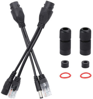
Parts list:
- 1x Passive PoE receiver
- 1x Passive PoE injector
- 1x 30m LAN cable
Here we'll discuss passive PoE (Power-over-Ethernet). It's a standard that allows you to send quite high voltages (ex: 48V DC) over standard ethernet cables, alongside data using other pairs of wires. It has the great property that connecting non-PoE devices to will cause no harm, unlike our RJ-45 setup above.
The disadvantage is passive PoE components are quite expensive, and we're still limited to the maximum current rating for the RJ-45 wire (1 of 8 wires in the cable). Passive PoE would work as a quick solution with minimal components, but the costs are not interesting and the power is too limited.
Overall, this is a bad solution.
RS-485
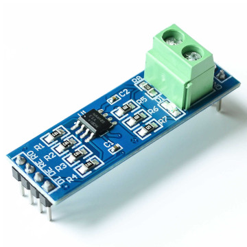
Parts list:
- 2x RJ-45 connectors
- 1x 30m LAN cable
- 2x RS-485 transceiver modules
- 1x bypass capacitor
- 2x 500mA fuses
- 2x PCBs to solder/wire the RS-485, capacitors, and RJ-45 connectors
The RS-485 standard is designed to send data over a differential pair (twisted pair), in other words: 2 wires. There exists multiple RS-485 transceivers by many companies with various parameters. The idea is similar to the RJ-45 solution, except we're using 6 wires instead of 3 (one pair for data, power, ground). This significantly increases the reliability of the signal and can work perfectly over 30 meters, and it even allows you to draw 2x more power, but it also has some drawbacks.
The first problem is of safety: if you decide to draw 700mA and split it across the two power wires, and there's a short in your circuit (ex: a rodent eats through 1 of the power wires), then you'll end up drawing 700mA through the remaining wire (rated for 350mA). Again this will heat up the LAN cable and possibly catch fire.
The next problem is of hardware: You'll need to add some filtering capacitors close to the LEDs, and you'll need more wiring to connect the RS-485 devices to your LEDs and microcontroller. It can quickly start to get messy.
Overall, this is not a bad solution, but it requires many more hardware components and doesn't help for powering larger loads (at least not without a fire hazard).
CAN Bus
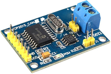
Parts list:
- Same as RS-485, except replace RS-485 modules with CAN Bus modules
The CAN bus modules are quite similar to RS-485 (differential signaling), except they also include the protocol layer, which means there's a much lower firmware requirement. You can interface with modules over SPI and move-on. This is the most reliable and flexible solution so far, but CAN Bus modules cost more than RS-485 and require more power as well.
Overall, this is a good approach when you don't want to implement a custom protocol. It's also good if you want to incorporate multiple devices, sensors, etc, however it's perhaps a bit overkill for our use-case and still doesn't solve the power problem.
TOSLINK
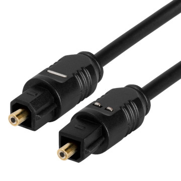
Parts list:
- 2x TOSLINK connectors
- 1x TOSLINK cable
Toshiba's TOSLINK is another standard that's been suggested on the internet. Although I admit fiber optics are the bees knees when it comes to transmitting data reliably over long distances, TOSLINK itself is less than optimal. The cables are not designed for long distances, and they're quite expensive. They also require special connectors at both ends, which are quite pricey and hard to find.
TOSLINK's advantage is that it's reliable, but it won't work over a distance of more than 10m. In fact, you'd be hard pressed to find a decently priced cable longer than 5m. Unfortunately you can't send power over the TOSLINK cable, so another idea is needed.
Overall, this is a bad solution.
DIY Fiber optic
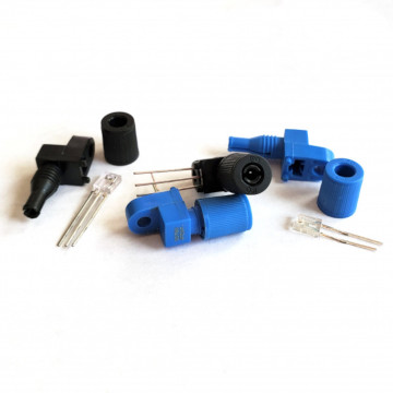 Image is Copyright Sparkfun - CC BY 2.0
Parts list:
- 2x superbright red LEDs
- 2x photodiodes or phototransistors
- 2x 30m fiber optic cables
- 2x 30m AWG16 cables
- 1x 4A fuse
- Handful of bypass capacitors and resistors
With a simple LED and photodiode at each end, we can send and receive data between devices without the drawbacks of distance, EMI, or unreliability. The data can be transmitted using any custom serial protocol (ex: UART).
Since we can't send power over fiber optics, we'll send power (and ground) over separate low gauge cables. AWG16 is rated for 3.7A for power transmission, which should be more than enough to safely power 5m of LEDs. In that case, a larger fuse should be used to protect the power cable.
Although fiber optic cables can vary in cost, no other hardware components are required, so there's very minimal effort to get up and running. Wiring the LED and photodiode/phototransistor is relatively straightforward and you can pretty much forget it once it's up and running.
Overall, this is my favourite solution, albeit somewhat expensive compared to others.
Other
I'm assuming there are other solutions out there which I haven't explored in this post, but they are likely antiquated or too obscure to be of interest.
What to buy
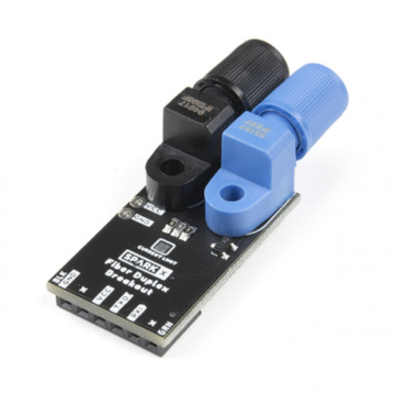 Image is Copyright Sparkfun - CC BY 2.0
I can recommend Sparkfun's Fiber Duplex Board for absolute beginners, but you'll likely save more money buying LEDs and photodiodes directly from Industrial Fiber Optics, or just making your own using 3D printed housings.
Closing notes
Our end goal was achieved by using separate cabling (fiber) for data and cabling (copper) for power. This prevents many issues, is reliable, simple, safe, and works over long distances. The trade-off is cost, but as more and more people are switching to fiber networking, I have a feeling the cost of these components will continue to decrease.
https://blog.a1w.ca/p/2021-03-08-simple-and-low-cost-ways-to-transmit-data-over-long-wires-with-a-microcontroller
2021-03-08 05:09:29 UTC